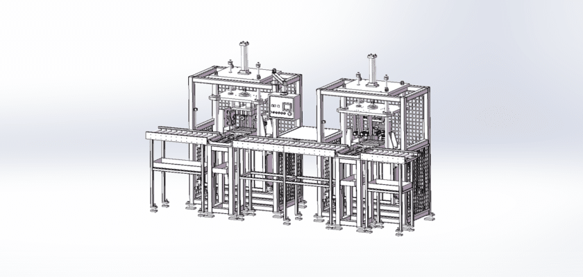
An Engine Cylinder Air and Water Detection Device Drawing is a technical illustration that outlines the components and layout of a device designed to monitor air and water presence in engine cylinders.
Key Features:
- Detection Sensors: Diagrams of the sensors used to detect air and water levels, such as pressure sensors, humidity sensors, or capacitive sensors, with indications of their placement within the engine assembly.
- Measurement Chamber: Representation of the chamber where air and water are sampled for analysis, highlighting any features that ensure accurate readings.
- Control Unit: Details of the processing unit that interprets sensor data, manages detection processes, and communicates with the engine control system.
- User Interface: Illustrations of the control panel or digital display that allow operators to monitor readings, adjust settings, and receive alerts regarding air and water levels.
- Connectivity Features: Diagrams showing how the device interfaces with the engine management system, including data transmission methods such as CAN bus or serial communication.
- Power Supply: Information regarding the power requirements for the device, including connections to the vehicle’s electrical system or standalone power sources.
- Mechanical Housing: Details about the casing that protects the internal components from engine vibrations, heat, and environmental factors, ensuring durability and reliability.
This drawing serves as a crucial reference for engineers and technicians involved in the design, assembly, and maintenance of engine cylinder air and water detection devices, contributing to improved engine performance and reliability.