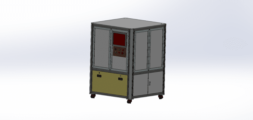
An Automatic Visual Inspection Machine Drawing is a technical illustration that outlines the components and layout of a machine designed for automated visual inspection of products or components.
Key Features:
- Inspection Station: Diagrams showing the area where items are positioned for visual inspection, often featuring adjustable fixtures or conveyor systems to ensure proper alignment.
- Camera System: Representation of the cameras used for capturing images, including their placement, lenses, and any lighting systems (like LEDs) that enhance image quality.
- Image Processing Unit: Details of the processing unit that analyzes captured images, using algorithms to detect defects, measure dimensions, and assess overall quality.
- User Interface: Illustrations of the control panel or touchscreen that allows operators to monitor the inspection process, set parameters, and view inspection results in real-time.
- Data Output Systems: Diagrams showing how inspection results are communicated, such as through digital displays, alerts for defects, or data logging systems for quality analysis.
- Mechanical Handling System: Information about the conveyor belt or robotic arms that transport items through the inspection area, ensuring smooth and efficient operation.
- Power Supply: Details regarding the power requirements for the machine, including electrical connections and any backup systems to ensure continuous operation.
This drawing serves as a comprehensive reference for engineers and technicians involved in the design, assembly, and maintenance of automatic visual inspection machines, ensuring effective quality control and operational efficiency in manufacturing processes.