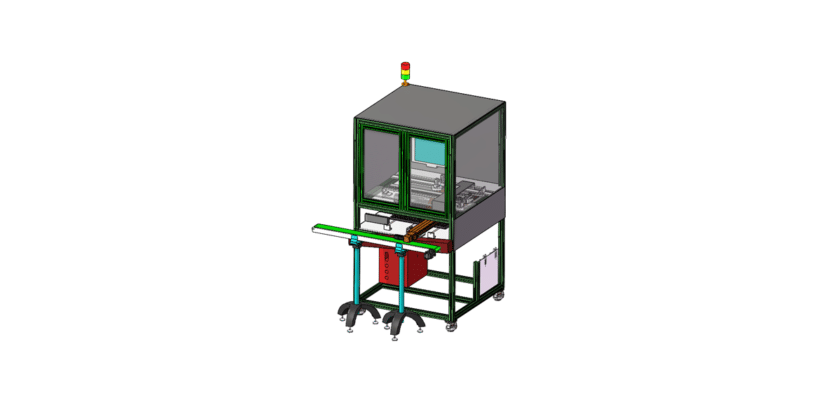
A Leakage Detection Machine Drawing is a technical illustration that outlines the components and layout of a machine designed to identify and measure leaks in various systems, such as pipes, tanks, or enclosures.
Key Features:
- Inspection Area: Diagrams showing the designated space where items are placed for leakage testing, often featuring fixtures or clamps that securely hold the components during the inspection process.
- Detection Sensors: Representation of the sensors used to detect leaks, which may include pressure sensors, ultrasonic sensors, or gas detectors, indicating their placement for optimal sensitivity and accuracy.
- Control Unit: Information on the processing unit that manages the testing operations, analyzes sensor data, and determines the presence and severity of leaks.
- User Interface: Illustrations of the control panel or touchscreen that allows operators to monitor the testing process, set parameters, and view real-time results and alerts.
- Data Output Systems: Diagrams showing how test results are displayed or logged, including digital displays, alarms for detected leaks, and connections to data management systems for reporting and analysis.
- Mechanical Framework: Details about the structural components that support the machine, ensuring stability and precision during inspections, including mounts or enclosures for sensors.
- Handling System: Information about any conveyor systems or automated mechanisms that transport items through the inspection area, ensuring efficient processing and minimizing handling errors.
- Power Supply: Details regarding the power requirements, including electrical connections and any backup systems to ensure reliable operation.
This drawing serves as a comprehensive reference for engineers and technicians involved in the design, assembly, and maintenance of leakage detection machines, ensuring effective quality control and operational efficiency in various applications.