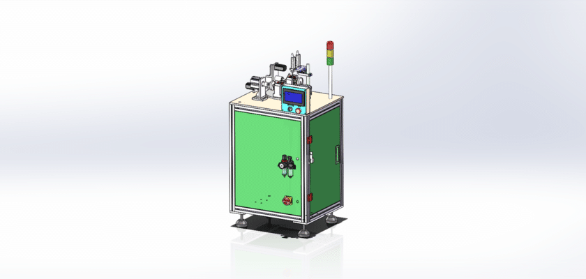
A Motor Detection Coil Equipment Drawing is a technical illustration that outlines the components and layout of a system designed to inspect and test coils in electric motors.
Key Features:
- Inspection Station: Diagrams showing the designated area where motor coils are placed for testing, featuring fixtures or clamps that securely hold the coils during inspection.
- Coil Testing Mechanism: Representation of the equipment used to apply electrical tests to the coils, including connections for measuring resistance, inductance, and other electrical parameters.
- Detection Sensors: Details about the sensors used to monitor electrical characteristics, such as current sensors, voltage probes, or temperature sensors, indicating their placement for optimal accuracy.
- Control Unit: Information on the processing unit that manages testing operations, records measurements, and analyzes data to assess coil quality and performance.
- User Interface: Illustrations of the control panel or touchscreen that allow operators to interact with the equipment, set parameters for tests, and view real-time results.
- Data Output Systems: Diagrams showing how inspection results are communicated, including digital displays for immediate feedback, logging systems for quality assurance, and connections for data management and reporting.
- Mechanical Framework: Information about the structural components that support the inspection system, ensuring stability and precision during testing operations.
- Power Supply: Details regarding the power requirements, including electrical connections and any backup systems to ensure reliable operation.
This drawing serves as a comprehensive reference for engineers and technicians involved in the design, assembly, and maintenance of motor detection coil equipment, ensuring effective quality control and performance evaluation in electric motor manufacturing processes.