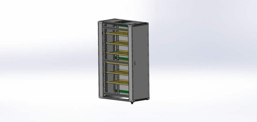
Download the comprehensive mechanical drawing for a Communication Cabinet, the fundamental enclosure for modern IT and telecommunications infrastructure. This versatile blueprint represents a standard cabinet design used to safely house, organize, and protect critical equipment such as servers, switches, routers, patch panels, and fiber optic termination units.
This high-quality CAD drawing is an indispensable resource for network engineers, facility managers, and system integrators. It provides the precise dimensional data required for accurate space planning in data closets, server rooms, or co-location facilities. Use this file to meticulously plan your equipment layout, manage U-space allocation, and engineer efficient cable routing pathways.
Our drawing details all the critical construction elements, from the load-bearing frame to the mounting rails and ventilation cutouts. By integrating this drawing into your master facility plans, you can verify all spatial clearances, plan for thermal management and airflow, and ensure your installation is clean, professional, and compliant. This blueprint is perfect for designing a new network deployment, retrofitting an existing space, or fabricating a custom enclosure.
الميزات الرئيسية:
- Standard 19-Inch Rails: Details the precise location and E-marked U-spacing of the 19″ vertical mounting rails.
- Frame and Structure: Shows the complete cabinet assembly (welded or bolted), including dimensions for overall height, width, and depth.
- Cable Entry Points: Clearly identifies cutouts and gland plate areas on the top and bottom panels for high-volume cable management.
- Ventilation and Cooling: Includes details on perforated doors (front and rear) and fan tray mounting points for optimal thermal airflow.
- Access and Security: Illustrates removable side panels and a lockable front door with hinge and swing-direction details.