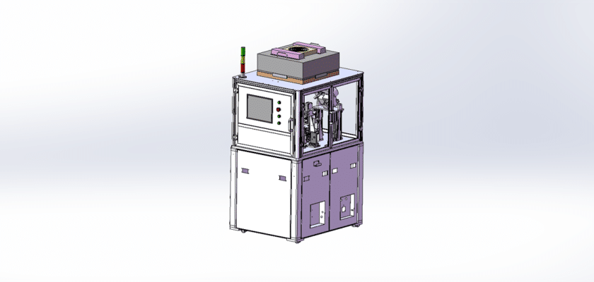
رسم معدات الكشف عن العمود المرفقي هو رسم توضيحي تقني يوضح مكونات وتخطيط الآلات المصممة لفحص وتقييم جودة العمود المرفقي في التطبيقات الصناعية والسيارات.
الميزات الرئيسية:
- محطة التفتيش:رسوم بيانية توضح المنطقة التي يتم وضع أعمدة الكرنك فيها للفحص، وغالبًا ما تحتوي على تركيبات أو مشابك لتأمين عمود الكرنك أثناء الفحص.
- أجهزة استشعار القياس:تمثيل المستشعرات المستخدمة لتقييم المعلمات المختلفة مثل الاستقامة والانحراف والأبعاد، والتي قد تشمل أنظمة قياس بالليزر أو مؤشرات الاتصال.
- وحدة التحكم:تفاصيل وحدة المعالجة التي تدير عمليات التفتيش، وتحلل بيانات المستشعر، وتقدم ردود الفعل حول حالة العمود المرفقي.
- واجهة المستخدم:رسوم توضيحية للوحة التحكم أو شاشة اللمس التي تسمح للمشغلين بمراقبة عملية التفتيش وتعيين المعلمات وعرض النتائج في الوقت الفعلي.
- أنظمة إخراج البيانات:رسوم بيانية توضح كيفية عرض نتائج التفتيش أو تسجيلها، بما في ذلك الشاشات الرقمية، والطابعات للتقارير، أو الاتصالات بأنظمة إدارة البيانات لمزيد من التحليل.
- نظام المناولة الميكانيكية:معلومات عن أنظمة النقل أو الروبوتات التي تنقل أعمدة العمود المرفقي عبر منطقة التفتيش، مما يضمن المعالجة الفعالة ويقلل من أخطاء المناولة.
- مزود الطاقة:تفاصيل بشأن متطلبات الطاقة، بما في ذلك التوصيلات الكهربائية وأي أنظمة احتياطية للحفاظ على التشغيل المستمر.
يُعد هذا الرسم بمثابة مرجع شامل للمهندسين والفنيين المشاركين في تصميم وتجميع وصيانة معدات الكشف عن العمود المرفقي، مما يضمن معايير عالية لمراقبة الجودة والكفاءة التشغيلية في عمليات التصنيع.