أ رسم آلة القطع والضغط هو مخطط فني يُقدم مواصفات مفصلة للآلات المستخدمة في عمليات القطع والضغط في مختلف الصناعات. تُعدّ هذه الرسومات أدوات أساسية للمهندسين والمصممين والمصنّعين، حيث تُقدّم رؤى واضحة حول تصميم المعدات وأبعادها ووظائفها. يضمن الرسم المُصمّم جيدًا للآلة التكامل الفعال لوظائف القطع والضغط في آلة واحدة، مما يُعزز كفاءة التشغيل.
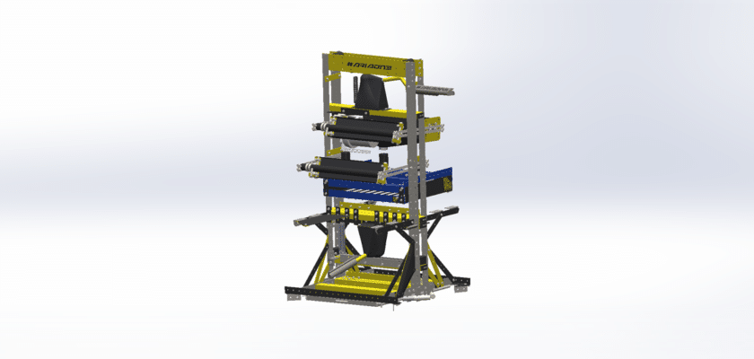
الميزة الأساسية لـ آلة القطع والضغط تتميز هذه الآلات بوظيفتها المزدوجة، حيث يمكنها أداء مهام القطع والضغط، مما يجعلها مثالية لصناعات مثل تشغيل المعادن والبلاستيك والسيارات والتغليف. صُممت هذه الآلات للتعامل مع المواد الصلبة، مما يوفر قطعًا وتشكيلًا دقيقين مع الحفاظ على إنتاجية عالية. عادةً ما يُبرز رسم الآلة المكونات الرئيسية، بما في ذلك شفرات القطع، وألواح الضغط، والأنظمة الهيدروليكية، وميزات السلامة.
من الجوانب المهمة الأخرى في الرسومات التخطيطية تصميم تشغيل الآلة. يستطيع المهندسون تقييم مواقع مكونات مثل المحركات والتروس ولوحات التحكم، مما يضمن محاذاة الآلة بشكل صحيح وسهولة تشغيلها. تتضمن الرسومات أبعادًا ومواصفات مواد وتفاوتات تفصيلية لضمان ملاءمة كل جزء تمامًا داخل الآلة، مما يؤدي إلى أداء مثالي.
بالإضافة إلى تفاصيلها الفنية، رسم آلة القطع والضغط قد تتضمن تعليمات التجميع والصيانة، مما يُمكّن المُشغّلين من إعداد الآلات وضبطها وصيانتها بسهولة. وتلعب هذه الرسومات دورًا حاسمًا في ضمان تشغيل الآلة بسلاسة وأمان، مع أقل قدر من التوقف، وهو أمرٌ أساسي للحفاظ على الإنتاجية في البيئات الصناعية.