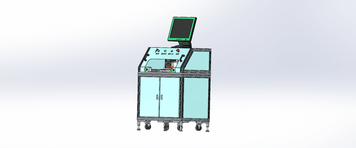
رسم آلة فحص التسطيح هو رسم توضيحي تقني يوضح مكونات وتخطيط آلة مصممة لقياس والتحقق من تسطيح الأسطح أو المواد المختلفة.
الميزات الرئيسية:
- منصة القياس:رسوم بيانية للسطح المستوي حيث يتم وضع العناصر للفحص، وغالبًا ما تتميز بأنظمة تسوية دقيقة لضمان تقييمات دقيقة.
- نظام الاستشعار:تمثيل أجهزة الاستشعار المستخدمة للكشف عن الانحرافات في التسطيح، مثل الماسحات الضوئية بالليزر، أو أجهزة الاستشعار البصرية، أو مؤشرات الاتصال، بما في ذلك مواضعها للحصول على تغطية مثالية.
- وحدة التحكم:تفاصيل وحدة المعالجة التي تدير عمليات القياس، وتعالج البيانات من أجهزة الاستشعار، وتتحكم في سير عمل التفتيش.
- واجهة المستخدم:رسوم توضيحية للوحة التحكم أو شاشة اللمس التي تسمح للمشغلين بتعيين المعلمات وبدء عمليات التفتيش وعرض النتائج في الوقت الفعلي.
- أنظمة إخراج البيانات:الرسوم البيانية التي توضح كيفية عرض نتائج القياس أو تسجيلها، بما في ذلك الشاشات الرقمية، أو الطابعات للتقارير، أو الاتصالات بأنظمة إدارة البيانات.
- الإطار الميكانيكي:معلومات عن المكونات الهيكلية التي تدعم منصة القياس وأجهزة الاستشعار، مما يضمن الاستقرار والدقة أثناء عمليات التفتيش.
- مزود الطاقة:تفاصيل بشأن متطلبات الطاقة، بما في ذلك التوصيلات الكهربائية وأي أنظمة احتياطية للحفاظ على التشغيل أثناء عمليات التفتيش.
يُعد هذا الرسم بمثابة مرجع شامل للمهندسين والفنيين المشاركين في تصميم وتجميع وصيانة آلات فحص التسطيح، مما يضمن معايير عالية لمراقبة الجودة والدقة في عمليات التصنيع.