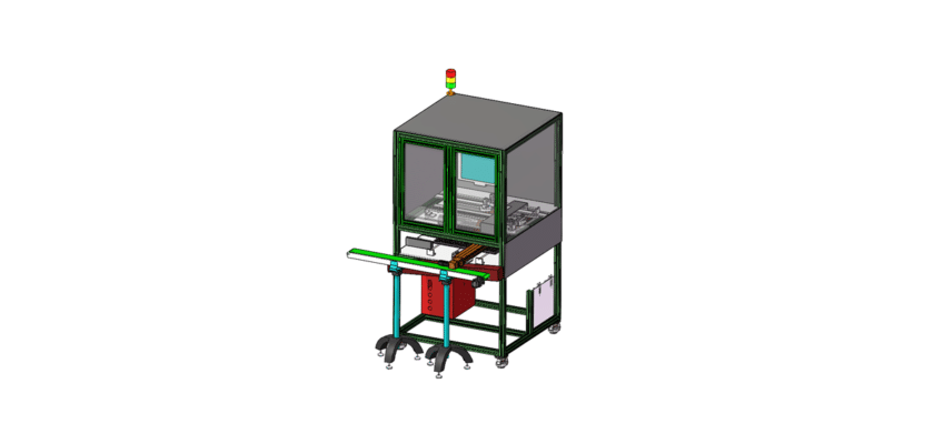
رسم جهاز كشف التسرب هو رسم توضيحي تقني يوضح مكونات وتخطيط الجهاز المصمم لتحديد وقياس التسربات في أنظمة مختلفة، مثل الأنابيب أو الخزانات أو الحاويات.
الميزات الرئيسية:
- منطقة التفتيش:رسوم بيانية توضح المساحة المخصصة لوضع العناصر لاختبار التسرب، وغالبًا ما تحتوي على تركيبات أو مشابك تثبت المكونات بشكل آمن أثناء عملية التفتيش.
- أجهزة استشعار الكشف:تمثيل أجهزة الاستشعار المستخدمة للكشف عن التسربات، والتي قد تشمل أجهزة استشعار الضغط، أو أجهزة استشعار الموجات فوق الصوتية، أو أجهزة كشف الغاز، مع الإشارة إلى موضعها للحصول على حساسية ودقة مثالية.
- وحدة التحكم:معلومات عن وحدة المعالجة التي تدير عمليات الاختبار، وتحلل بيانات المستشعر، وتحدد وجود التسريبات وشدتها.
- واجهة المستخدم:رسوم توضيحية للوحة التحكم أو شاشة اللمس التي تسمح للمشغلين بمراقبة عملية الاختبار، وتعيين المعلمات، وعرض النتائج والتنبيهات في الوقت الفعلي.
- أنظمة إخراج البيانات:رسوم بيانية توضح كيفية عرض نتائج الاختبار أو تسجيلها، بما في ذلك الشاشات الرقمية، وأجهزة الإنذار الخاصة بالتسريبات المكتشفة، والاتصالات بأنظمة إدارة البيانات لإعداد التقارير والتحليل.
- الإطار الميكانيكي:تفاصيل حول المكونات الهيكلية التي تدعم الماكينة، وتضمن الاستقرار والدقة أثناء عمليات التفتيش، بما في ذلك الحوامل أو الحاويات الخاصة بأجهزة الاستشعار.
- نظام المناولة:معلومات عن أي أنظمة ناقلة أو آليات آلية تنقل العناصر عبر منطقة التفتيش، مما يضمن المعالجة الفعالة ويقلل من أخطاء المناولة.
- مزود الطاقة:تفاصيل بشأن متطلبات الطاقة، بما في ذلك التوصيلات الكهربائية وأي أنظمة احتياطية لضمان التشغيل الموثوق به.
يعد هذا الرسم بمثابة مرجع شامل للمهندسين والفنيين المشاركين في تصميم وتجميع وصيانة آلات الكشف عن التسرب، مما يضمن مراقبة الجودة الفعالة والكفاءة التشغيلية في مختلف التطبيقات.