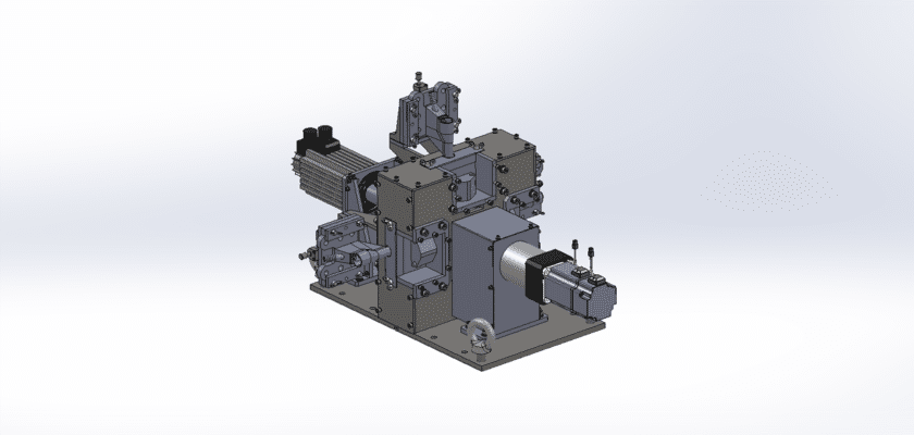
A Sensor Inspection Drawing is a technical illustration that outlines the components and layout of a system designed for the inspection and testing of various sensors. This drawing is crucial for ensuring the quality and performance of sensors used in different applications.
الميزات الرئيسية:
- محطة التفتيش: Diagrams showing the designated area where sensors are placed for evaluation, featuring fixtures or holders that securely position the sensors during testing.
- معدات الاختبار: Representation of the devices used to assess sensor functionality and performance, such as multimeters, calibration tools, or specialized testing rigs for different sensor types (e.g., temperature, pressure, or proximity sensors).
- وحدة التحكم: Information on the processing unit that manages the inspection operations, records measurements, and analyzes data to ensure compliance with quality standards.
- واجهة المستخدم:رسوم توضيحية للوحة التحكم أو شاشة اللمس التي تسمح للمشغلين بمراقبة عملية التفتيش وتعيين المعلمات وعرض النتائج في الوقت الفعلي.
- أنظمة إخراج البيانات: Diagrams showing how inspection results are communicated and logged, including digital displays for immediate feedback, data storage for quality analysis, and connections for reporting to external systems.
- الإطار الميكانيكي:معلومات عن المكونات الهيكلية التي تدعم نظام التفتيش، وتضمن الاستقرار والدقة أثناء التشغيل.
- مزود الطاقة: Details regarding the power requirements, including electrical connections and backup systems to maintain reliable operation.
This drawing serves as a comprehensive reference for engineers and technicians involved in the design, assembly, and maintenance of sensor inspection systems, ensuring high standards of quality control and operational efficiency in manufacturing and testing processes.