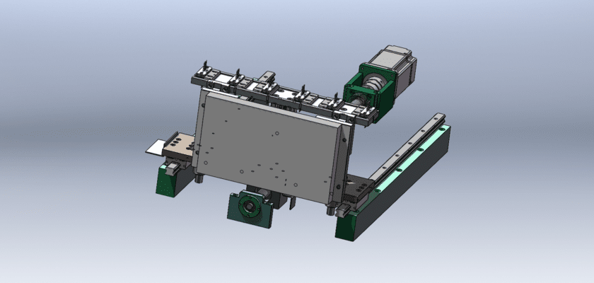
A Detection Part Drawing is a technical illustration that outlines the specific components involved in a detection system, focusing on the individual parts responsible for identifying and analyzing various elements or anomalies.
Key Features:
- Sensor Components: Diagrams of various sensors (e.g., optical, ultrasonic, or thermal) that are integral to the detection process, highlighting their placement and function.
- Circuit Layout: Representation of the electronic circuitry that connects and powers the detection components, including resistors, capacitors, and microcontrollers.
- Mounting Fixtures: Details of the brackets or enclosures that hold the detection parts in place, ensuring stability and proper alignment during operation.
- User Interface Elements: Illustrations of any buttons, displays, or indicators associated with the detection part, allowing for user interaction and feedback.
- Data Output Connections: Diagrams showing interfaces for data transmission, such as ports for connecting to computers or other systems for further processing and analysis.
- Power Supply Connections: Information on how the detection part is powered, including specifications for power sources and any required connectors.
This drawing serves as a crucial reference for engineers and technicians involved in the design, assembly, and maintenance of detection systems, ensuring precise functionality and effective performance across various applications.