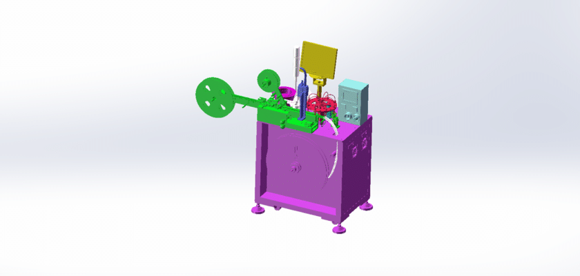
A Pull-Out Force Detection Machine Drawing is a technical illustration that outlines the components and layout of a machine designed to measure the pull-out force of various materials or components, often used in quality control and testing applications.
Características principales:
- Estación de pruebas: Diagrams showing the area where samples are placed for testing, including fixtures or clamps that securely hold the materials during the pull-out process.
- Force Measurement Sensors: Representation of the sensors (such as load cells or strain gauges) used to accurately measure the pull-out force exerted on the sample during testing.
- Unidad de control: Details of the processing unit that manages the testing operations, records measurements, and analyzes data to determine the pull-out force characteristics.
- Interfaz de usuario: Illustrations of the control panel or touchscreen that allows operators to set parameters, monitor the testing process, and view results in real-time.
- Sistemas de salida de datos: Diagrams showing how test results are displayed or logged, including digital displays, printers for reports, or connections to data management systems for further analysis.
- Marco mecánico: Information about the structural components that support the testing apparatus, ensuring stability and precision during measurements.
- Fuente de alimentación:Detalles sobre los requisitos de energía, incluidas las conexiones eléctricas y cualquier sistema de respaldo para garantizar un funcionamiento confiable.
This drawing serves as a comprehensive reference for engineers and technicians involved in the design, assembly, and maintenance of pull-out force detection machines, ensuring accurate testing and quality assurance in manufacturing processes.