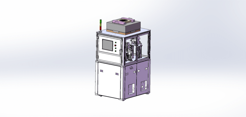
Un dibujo de equipo de detección de cigüeñal es una ilustración técnica que describe los componentes y el diseño de la maquinaria diseñada para inspeccionar y evaluar la calidad de los cigüeñales en aplicaciones automotrices e industriales.
Características principales:
- Estación de inspección:Diagramas que muestran el área donde se colocan los cigüeñales para su examen, a menudo presentan accesorios o abrazaderas que aseguran el cigüeñal durante la inspección.
- Sensores de medición:Representación de los sensores utilizados para evaluar diversos parámetros como rectitud, excentricidad y dimensiones, que pueden incluir sistemas de medición láser o indicadores de cuadrante.
- Unidad de control:Detalles de la unidad de procesamiento que gestiona las operaciones de inspección, analiza los datos de los sensores y proporciona retroalimentación sobre el estado del cigüeñal.
- Interfaz de usuario:Ilustraciones del panel de control o pantalla táctil que permite a los operadores monitorear el proceso de inspección, establecer parámetros y ver resultados en tiempo real.
- Sistemas de salida de datos:Diagramas que muestran cómo se muestran o registran los resultados de la inspección, incluidas pantallas digitales, impresoras para informes o conexiones a sistemas de gestión de datos para análisis posteriores.
- Sistema de manipulación mecánica:Información sobre los sistemas transportadores o robóticos que transportan los cigüeñales a través del área de inspección, garantizando un procesamiento eficiente y minimizando errores de manipulación.
- Fuente de alimentación:Detalles sobre los requisitos de energía, incluidas las conexiones eléctricas y cualquier sistema de respaldo para mantener un funcionamiento constante.
Este dibujo sirve como una referencia integral para ingenieros y técnicos involucrados en el diseño, ensamblaje y mantenimiento de equipos de detección de cigüeñal, asegurando altos estándares de control de calidad y eficiencia operativa en los procesos de fabricación.