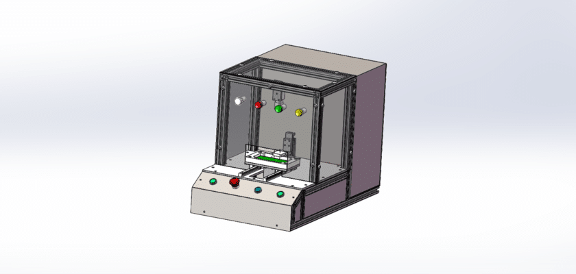
Un dibujo de inspección visual de LED es una ilustración técnica que detalla los componentes y el diseño de un sistema diseñado para la inspección visual utilizando tecnología de iluminación LED.
Características principales:
- Área de inspección:Diagramas que muestran el espacio designado donde se colocan los artículos para inspección visual, a menudo con accesorios o plataformas ajustables para garantizar la alineación y estabilidad adecuadas.
- Sistema de iluminación LED:Representación de las luces LED utilizadas para iluminar el área de inspección, incluidos detalles sobre su ubicación, tipo (por ejemplo, luces de anillo, focos) y cualquier característica ajustable que mejore la visibilidad y minimice las sombras.
- Cámara o sistema de imágenes:Detalles sobre las cámaras o sensores de imágenes que capturan imágenes de alta resolución de los objetos que se inspeccionan, ilustrando su posicionamiento para una cobertura y claridad óptimas.
- Unidad de control:Información sobre la unidad de procesamiento que gestiona el proceso de inspección, analiza las imágenes capturadas por la cámara y detecta defectos o anomalías mediante algoritmos de procesamiento de imágenes.
- Interfaz de usuario:Ilustraciones del panel de control o pantalla táctil que permite a los operadores monitorear el proceso de inspección, ajustar configuraciones y ver resultados en tiempo real.
- Sistemas de salida de datos:Diagramas que muestran cómo se comunican los resultados de la inspección, incluidas pantallas digitales para retroalimentación inmediata, sistemas de registro para control de calidad y conexiones a sistemas de gestión de datos para análisis posteriores.
- Marco mecánico:Información sobre los componentes estructurales que soportan el sistema de inspección, garantizando estabilidad y precisión durante la operación.
- Fuente de alimentación:Detalles sobre los requisitos de energía, incluidas las conexiones eléctricas y cualquier sistema de respaldo para garantizar un funcionamiento confiable.
Este dibujo sirve como una referencia integral para ingenieros y técnicos involucrados en el diseño, ensamblaje y mantenimiento de sistemas de inspección visual LED, garantizando un control de calidad efectivo y una eficiencia operativa en diversas aplicaciones.