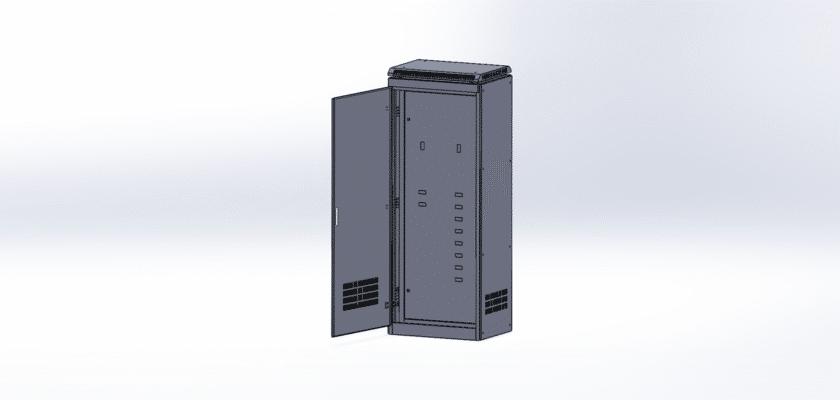
This is the essential 3D drawing for the GGD Low-Voltage Switchgear Cabinet, specifically detailed for the 1800x700x500 GGD form factor. The GGD-type cabinet is a highly reliable, standardized, and cost-effective solution for power distribution centers (PCC) and motor control centers (MCC) in industrial plants, substations, and large commercial buildings. It is a fixed-type assembly designed for low-voltage power distribution, illumination, and control.
This complete CAD model is a critical asset for electrical engineers, panel builders, and facility designers. It provides a precise, dimensionally accurate 3D representation, which is essential for planning the internal layout of busbars, main air circuit breakers (ACB), and molded case circuit breakers (MCCB). Use this drawing to optimize your panel build, ensure correct electrical and safety clearances, manage thermal dissipation, and accurately plan your power and control cable entry and exit points.
The 1800mm height provides ample space for complex feeder arrangements, while the 700mm width and 500mm depth offer a balanced footprint. Our free drawing is the perfect blueprint for fabrication or for integrating the cabinet into a larger electrical room layout. Download this high-quality GGD model today to accelerate your design-to-manufacture process and ensure a safe, compliant installation.
Caractéristiques principales :
- Precise 1800x700x500mm Model: A dimensionally accurate 3D model of the GGD enclosure, capturing the 1800mm height, 700mm width, and 500mm depth.
- GGD Standard Compliant: The design adheres to the structural principles of the GGD-type fixed low-voltage switchgear standard, known for its high breaking capacity and good thermal stability.
- Detailed Internal Structure: Includes the cabinet frame, mounting back panel, and clear space allocation for the main busbar compartment and functional unit compartments.
- Panel Builder Ready: Perfect for planning the layout of all internal components (breakers, contactors, meters, and PLCs), ensuring a precise fit and optimizing wiring paths.
- Format CAO universel : Supplied in a standard, compatible format (like .STEP or .IGES) for immediate use in SolidWorks, AutoCAD, Inventor, and other professional engineering software.