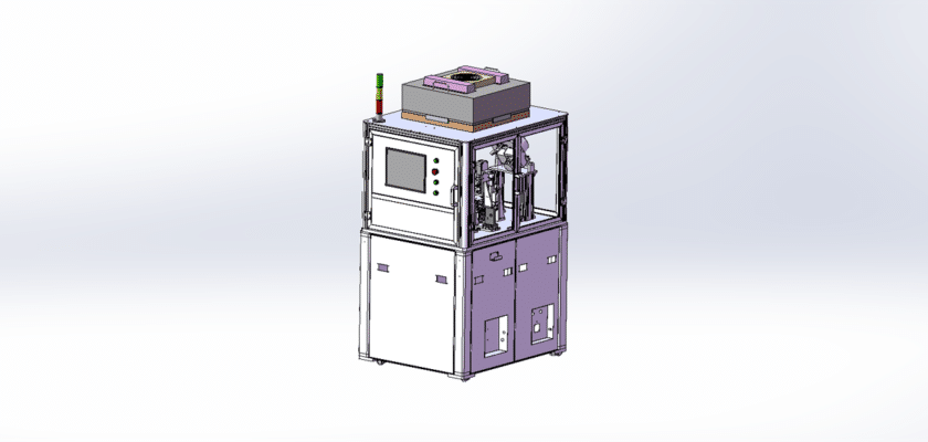
A Crankshaft Detection Equipment Drawing is a technical illustration that outlines the components and layout of machinery designed to inspect and assess the quality of crankshafts in automotive and industrial applications.
Caractéristiques principales :
- Poste d'inspection: Diagrams showing the area where crankshafts are positioned for examination, often featuring fixtures or clamps that secure the crankshaft during inspection.
- Capteurs de mesure: Representation of the sensors used to assess various parameters such as straightness, runout, and dimensions, which may include laser measuring systems or dial indicators.
- Unité de contrôle: Details of the processing unit that manages the inspection operations, analyzes sensor data, and provides feedback on the crankshaft’s condition.
- Interface utilisateur: Illustrations of the control panel or touchscreen that allows operators to monitor the inspection process, set parameters, and view results in real-time.
- Systèmes de sortie de données: Diagrams showing how inspection results are displayed or logged, including digital screens, printers for reports, or connections to data management systems for further analysis.
- Système de manutention mécanique: Information about the conveyor or robotic systems that transport crankshafts through the inspection area, ensuring efficient processing and minimizing handling errors.
- Alimentation électrique: Détails concernant les besoins en énergie, y compris les connexions électriques et tous les systèmes de secours pour maintenir un fonctionnement cohérent.
This drawing serves as a comprehensive reference for engineers and technicians involved in the design, assembly, and maintenance of crankshaft detection equipment, ensuring high standards of quality control and operational efficiency in manufacturing processes.