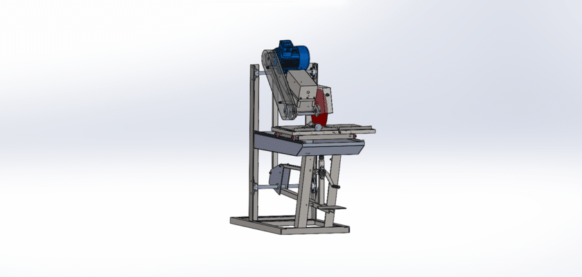
Le Dessin de machine de découpe Il s'agit d'une illustration technique détaillée illustrant la conception et la structure d'une machine de découpe. Ce dessin est un outil essentiel pour les ingénieurs, les concepteurs et les fabricants, offrant une vue d'ensemble complète des composants et des fonctionnalités de la machine. Il inclut généralement les spécifications de pièces telles que la lame de coupe, le moteur, le système d'entraînement, le châssis et le panneau de commande, permettant un assemblage et une maintenance efficaces.
La principale caractéristique de la machine de découpe, illustrée sur le dessin, est son mécanisme de coupe, conçu pour une précision et une cadence élevées. Le dessin illustre le positionnement des lames et leur interaction avec le matériau traité, garantissant des coupes précises et régulières à chaque fois. Il met également en valeur la conception ergonomique de la machine, qui simplifie son utilisation et minimise la fatigue de l'opérateur.
En plus des composants mécaniques, le Dessin de machine de découpe Il inclut souvent des schémas électriques illustrant le fonctionnement du système de contrôle. Cela permet aux opérateurs de comprendre les besoins énergétiques de la machine et de pouvoir dépanner ou réparer le système si nécessaire.
Globalement, le plan de machine de découpe est une référence indispensable pour toute personne impliquée dans la production, l'assemblage ou la maintenance de machines de découpe. Il fournit des informations essentielles pour garantir le bon fonctionnement de la machine, augmentant ainsi la productivité tout en minimisant les temps d'arrêt.