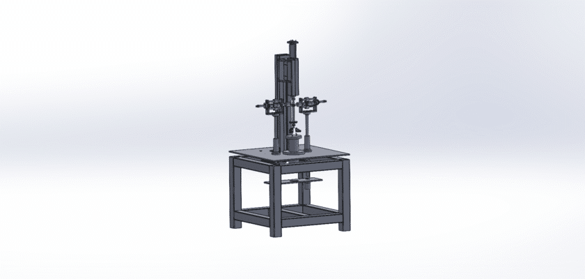
Unlock the power of precision gear manufacturing with our free Gear Cutting Machine drawing. This detailed CAD file is an essential resource for engineers, machinists, and designers in the automotive, aerospace, and heavy machinery industries. The drawing provides an in-depth look at a specialized machine designed to cut teeth into a blank gear with exceptional accuracy and consistency. Whether it’s a spur gear, helical gear, or worm gear, this machine is a critical tool for creating the components that power a vast range of mechanical systems.
The blueprint highlights the machine’s complex mechanisms, including the gear hob, the precision indexing table, and the synchronized drive system. Understanding these components is vital for anyone looking to build a custom machine, optimize a production line, or simply learn about the fundamental principles of gear hobbing. The design is optimized for continuous, high-speed operation, which is crucial for maximizing production throughput. Whether you are a student studying mechanical engineering or a professional seeking a reliable technical reference, this drawing is an invaluable tool to guide your next project.
Key Features:
- Precision Hobbing: The drawing details the process of using a hob to cut gear teeth with high accuracy and a consistent profile.
- Integrated Indexing: It showcases a precision indexing table that rotates the gear blank in perfect synchronization with the hob for flawless tooth cutting.
- Automated Workflow: The blueprint illustrates a design that can be integrated with an automated feeding system for continuous production.
- Versatile Applications: The machine’s design is applicable to a wide range of gear types and sizes, making it a flexible solution for various industries.
- Technical Specifications: Includes critical dimensions and specifications for the machine’s components, making it suitable for design and reference purposes.