In modern manufacturing, the twin processes of inspection and packaging are crucial for ensuring product quality and market readiness. Our free engineering drawings of an inspection and packaging machine offer an unparalleled glimpse into the sophisticated automation that makes this possible. This comprehensive resource is ideal for mechatronics students, professional engineers, and industrial designers who want to understand the integration of these complex systems. The detailed plans provide a complete overview of a fully automated process, from the initial quality check to the final sealing of the product, showcasing how precision and speed are achieved simultaneously.
The drawing set includes a variety of technical documents, such as detailed assembly schematics, component layouts, and a complete bill of materials. These files are a fantastic learning tool, providing a real-world example of how sensors, robotics, and mechanical systems work together to deliver a consistent, high-quality output. The drawings are meticulously crafted and compatible with all major CAD software, allowing you to easily view, analyze, and even modify the design for your own projects. Elevate your understanding of industrial automation with these professional-grade drawings, available for instant download at no cost.
Key Features:
- Integrated Inspection System: The drawings showcase the layout of vision systems and sensors for automatic defect detection, ensuring every product meets quality standards before packaging.
- Efficient Handling and Conveyance: Detailed plans illustrate the conveyor belts, robotic arms, and sorting mechanisms that move products seamlessly from the inspection stage to the packaging unit.
- Automated Packaging Unit: The documents provide a clear view of the forming, filling, and sealing mechanisms, detailing how materials are shaped and products are securely enclosed.
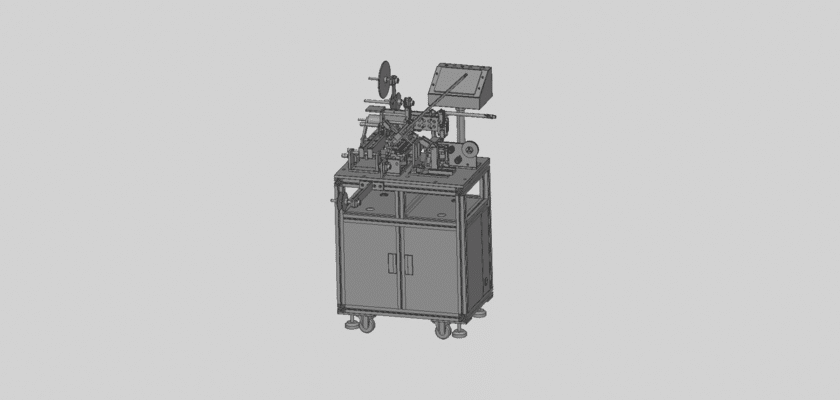
- Modular Design: The blueprints highlight a modular construction, making it easy to understand the function of each individual section—from the feeding hopper to the final ejection point.
- Control System Integration: Schematics demonstrate how the PLC (Programmable Logic Controller) or other control systems are wired to manage the machine’s various functions, ensuring synchronized and reliable operation.