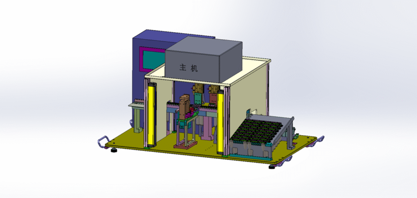
Unlock the secrets of circuit analysis with our free technical drawings for a Mini USB Tester. This essential tool is a must-have for electronics enthusiasts, engineers, and DIY hobbyists. The drawings provide a detailed look at the simple yet effective design of a device that measures voltage and current in USB-powered circuits. Understanding the schematics of this tester is key to troubleshooting power issues, evaluating device charging performance, and ensuring the safety of your electronics projects.
Our high-quality, CAD-compatible drawings are available for instant download at no cost. By studying these plans, you will gain a deeper appreciation for compact electronic design and the integration of components on a small circuit board. The blueprints are a perfect educational tool for learning about the principles of electrical measurement and the practical application of basic circuits. Whether you are building your own tester or simply want to understand how it works, this resource is an invaluable addition to your technical library. Download them today and start exploring the world of electronics.
Key Features:
- Compact Circuit Design: The drawings highlight the efficient layout of components on a small printed circuit board (PCB) suitable for a mini-tester form factor.
- Integrated Measurement Points: Blueprints show the precise location of shunts and resistors used to measure voltage and current with a digital display.
- Versatile Application: This design is applicable for understanding the testing of a wide range of USB-powered devices, from smartphones to microcontrollers.
- Educational Tool: A perfect resource for learning about basic electrical engineering principles and troubleshooting common electronic issues.
