Get the essential blueprint for the core of any fluid power system with this Hydraulic Power Unit Drawing, available for free, instant download only on MechStream. The Hydraulic Power Unit (HPU) acts as the heart and brain of a hydraulic system, converting electrical or mechanical energy into fluid pressure and flow to drive cylinders, motors, and other actuators. A well-designed HPU is critical for ensuring the reliable, precise, and efficient operation of industrial machinery, from presses and lifts to testing equipment.
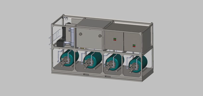
This comprehensive set of mechanical plans details the intricate layout and assembly of a typical HPU. It includes specifications for the reservoir, the proper mounting of the motor and pump assembly, and the complex integration of the valve manifold, filtration, and cooling systems. The drawing emphasizes thermal management, contamination control, and noise reduction—all vital factors for system longevity and performance. Whether you are a fluid power engineer, a maintenance technician, or a student of mechanical systems, this high-quality blueprint is an invaluable resource. Download the free Hydraulic Power Unit Drawing today to master the design principles behind these essential industrial power sources. MechStream provides expert, accessible plans for critical mechanical components.
Principais recursos:
- Reservoir Design and Volume: Detailed plans for the tank structure, including baffling, return line placement, and access panels for optimal fluid conditioning.
- Pump and Motor Assembly: Schematics for securely mounting the electric motor and pump, ensuring proper alignment and vibration dampening.
- Valve Manifold Integration: Precise drawing of the manifold block, detailing the location of pressure relief, directional control, and flow control valves.
- Filtration and Cooling Circuit: Specifications for incorporating essential filters and, where required, heat exchangers to maintain the fluid’s cleanliness and operating temperature.
- Instrumentation and Access Points: Plans showing the placement of pressure gauges, temperature probes, and test ports for monitoring and troubleshooting the system’s performance.