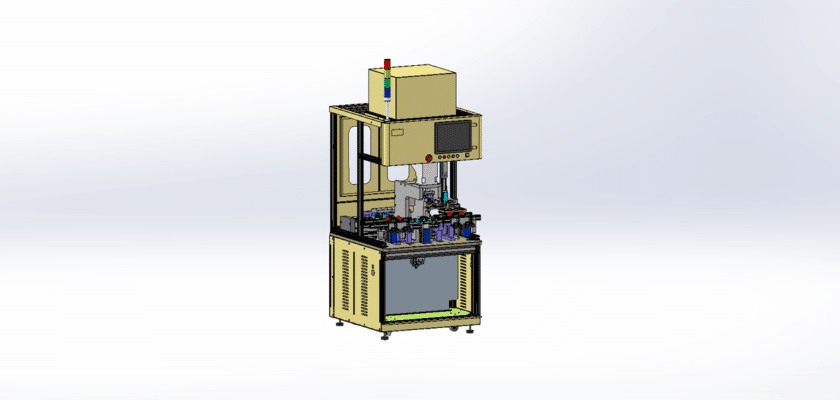
A Camera Detection Machine Drawing is a technical illustration that details the components and layout of a machine designed for visual detection and analysis using camera technology.
Principais recursos:
- Camera System: Diagrams showing the type of cameras used (e.g., CCD, CMOS) and their placement for optimal field of view, often including lenses and focus mechanisms.
- Lighting Setup: Representation of the lighting systems, such as LEDs or ring lights, that enhance image quality and visibility for accurate detection.
- Processing Unit: Details of the central processing unit or computer that analyzes the captured images, including software interfaces for image processing and data analysis.
- User Interface: Illustrations of the control panel or touchscreen where operators can adjust settings, monitor the detection process, and view results.
- Mechanical Framework: Information on the machine’s structural components, including mounts, enclosures, and any moving parts that facilitate camera positioning or image capture.
- Output Systems: Diagrams depicting how results are displayed, stored, or communicated, such as monitors, printers, or network connections for data transfer.
- Power Supply: Details regarding the power sources required for operation, including electrical connections and backup systems.
This drawing provides a comprehensive reference for engineers and technicians involved in the design, assembly, and maintenance of camera detection machines, ensuring effective performance in various applications such as quality control, surveillance, and automation.