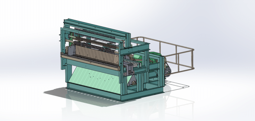
O Desenho da Máquina de Corte 1 fornece uma representação visual essencial do projeto da máquina, destacando seus principais componentes e características operacionais. É uma ferramenta indispensável para engenheiros, projetistas e fabricantes compreenderem a estrutura técnica e a funcionalidade da máquina. O desenho fornece especificações detalhadas para vários componentes, como lâminas de corte, motores, engrenagens e mecanismos de controle, garantindo uma fabricação precisa e uma montagem perfeita.
Este tipo de máquina é utilizado principalmente em indústrias que exigem cortes precisos de materiais como metais, plásticos e compósitos. Máquina de corte 1 foi projetada para desempenho em alta velocidade, oferecendo operações de corte confiáveis e eficientes. O desenho da máquina ilustra sua estrutura robusta, destacando a estrutura projetada para suportar altas tensões operacionais, garantindo a máxima precisão durante o processo de corte.
As principais características frequentemente representadas no desenho da máquina incluem o alinhamento do mecanismo de corte, os recursos de segurança e os controles operacionais. As dimensões e tolerâncias dos componentes da máquina são claramente indicadas para orientar os processos de fabricação. Também pode incluir instruções de montagem, permitindo rápida instalação e configuração da máquina em ambientes industriais.
Além disso, o Desenho da Máquina de Corte 1 Normalmente, descreve os requisitos de energia do sistema, os sistemas de lubrificação e as diretrizes de manutenção. Isso garante que a máquina opere de forma eficiente com tempo de inatividade mínimo, oferecendo confiabilidade a longo prazo em ambientes de produção de alta demanda. O desenho serve como uma referência crucial tanto para a configuração inicial quanto para a manutenção contínua, garantindo que a máquina opere sem problemas e com segurança durante todo o seu ciclo de vida.