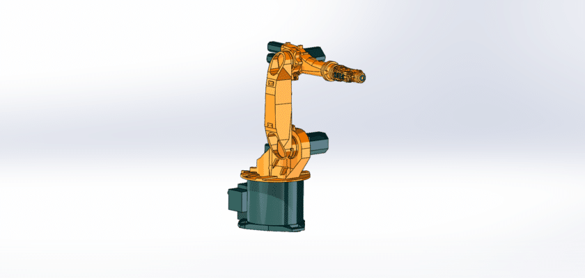
O Desenho do Braço Robótico D25 KR6 é uma ilustração técnica detalhada que descreve o design, os componentes e a funcionalidade do braço robótico D25 KR6. Este desenho é essencial para engenheiros, técnicos e operadores envolvidos na implantação, programação e manutenção deste modelo robótico específico.
Principais recursos:
- Layout geral:Uma visão abrangente do braço do robô D25 KR6, mostrando sua estrutura e design, incluindo configurações de juntas e capacidades de alcance.
- Configuração conjunta: Ilustrações detalhadas das articulações do braço, geralmente incluindo:
- Articulações Revolute: Descrições dos tipos de articulações que proporcionam movimento rotacional, permitindo posicionamento flexível.
- Graus de Liberdade: Informações sobre o número de graus de liberdade (GDL) que o braço fornece, essenciais para entender seu alcance operacional.
- Segmentos de braço: Diagramas mostrando os segmentos individuais do braço, incluindo:
- Comprimentos de link: Especificações sobre os comprimentos dos segmentos do braço, que determinam o alcance e o espaço de trabalho do robô.
- Composição do material: Informações sobre os materiais utilizados na construção, garantindo resistência e durabilidade.
- Sistema de Atuação: Descrições dos motores e atuadores usados para conduzir os movimentos do robô, incluindo:
- Servomotores: Detalhes sobre os tipos de servomotores empregados para controle preciso de cada articulação.
- Requisitos de energia: Especificações relativas aos requisitos elétricos para operar o robô.
- Efetor final: Informações sobre a ferramenta ou pinça fixada na extremidade do braço, projetada para tarefas específicas, como operações de coleta, posicionamento ou montagem.
- Sistema de controle: Detalhes sobre a unidade de controle que gerencia as operações do robô, incluindo:
- Interface de programação: Informações sobre o software usado para programar os movimentos e tarefas do robô.
- Protocolos de Comunicação: Descrições dos métodos de comunicação usados para interagir com o robô, como conexões Ethernet ou seriais.
- Recursos de segurança: Informações sobre mecanismos de segurança integrados, incluindo botões de parada de emergência, proteção contra sobrecarga e sensores que evitam acidentes durante a operação.
- Interface do usuário: Ilustrações de quaisquer painéis de controle ou telas sensíveis ao toque que forneçam aos operadores acesso às configurações do robô, modos operacionais e diagnósticos.
- Pontos de acesso de manutenção: Orientação sobre áreas projetadas para fácil acesso durante manutenção e reparo, facilitando a manutenção eficiente do robô.
- Especificações de desempenho: Resumo das principais métricas de desempenho, como capacidade de carga útil, alcance, velocidade e precisão, fornecendo informações essenciais para o planejamento operacional.
Este desenho serve como uma referência crucial para qualquer pessoa envolvida na operação e manutenção do braço robótico D25 KR6, garantindo desempenho eficaz, confiabilidade e aderência aos padrões da indústria em várias aplicações, incluindo fabricação, montagem e manuseio de materiais.