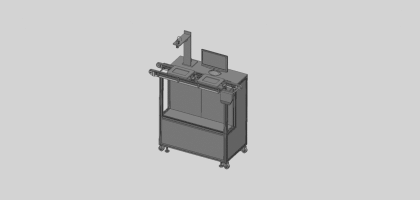
Um desenho de equipamento de detecção é uma ilustração técnica que detalha os componentes e o layout de máquinas projetadas para detectar elementos específicos ou anomalias em diversas aplicações.
Principais recursos:
- Mecanismo de detecção: Diagramas ilustrando os principais sensores ou sistemas de detecção utilizados (por exemplo, ópticos, ultrassônicos, infravermelhos) adaptados à aplicação específica.
- Instrumentos de Medição: Representação de dispositivos que capturam e analisam dados, como câmeras, microfones ou sondas especializadas.
- Unidade de controle: Detalhes sobre a unidade de processamento que interpreta dados dos sensores, executa algoritmos de processamento e gerencia as operações gerais do sistema.
- Interface do usuário: Ilustrações do painel de controle, incluindo telas, botões ou interfaces de toque que permitem aos operadores monitorar o desempenho e ajustar as configurações.
- Estrutura Mecânica: Informações sobre os componentes estruturais que abrigam o equipamento de detecção, incluindo suportes, gabinetes e quaisquer peças móveis.
- Sistemas de saída de dados: Diagramas que mostram como os dados detectados são relatados ou exibidos, como monitores, impressoras ou conexões de rede para transferência de dados.
- Fonte de energia: Detalhes sobre os requisitos e fontes de energia, incluindo conexões elétricas, baterias ou sistemas de backup para confiabilidade.
Este desenho serve como uma referência vital para engenheiros, técnicos e designers envolvidos no desenvolvimento, instalação e manutenção de equipamentos de detecção, garantindo operação eficaz e recursos de solução de problemas em vários setores.