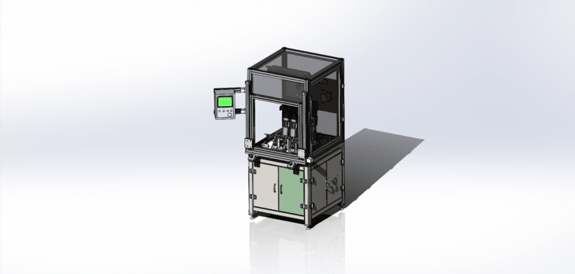
Um desenho de inspeção de alta tensão do cilindro principal é uma ilustração técnica que descreve os componentes e o layout de um sistema projetado para a inspeção de circuitos ou equipamentos de alta tensão dentro de um conjunto de cilindro principal, frequentemente usado em aplicações industriais.
Principais recursos:
- Área de Inspeção: Diagramas mostrando o espaço designado onde o cilindro principal é posicionado para inspeção, apresentando acessórios que o prendem durante o teste.
- Equipamentos de teste de alta tensão: Representação dos dispositivos usados para aplicar e medir níveis de alta tensão, incluindo testadores de isolamento, sondas de tensão e barreiras de segurança.
- Unidade de controle: Informações sobre a unidade de processamento que gerencia as operações de inspeção, monitora os níveis de tensão e registra dados dos equipamentos de teste.
- Interface do usuário: Ilustrações do painel de controle ou tela sensível ao toque que permitem aos operadores definir parâmetros de teste, monitorar o processo de inspeção e visualizar os resultados em tempo real.
- Recursos de segurança: Detalhes sobre mecanismos de segurança integrados ao sistema, como interruptores de desligamento de emergência, gabinetes de proteção e indicadores de advertência para garantir a segurança do operador durante testes de alta tensão.
- Sistemas de saída de dados: Diagramas mostrando como os resultados da inspeção são registrados e comunicados, incluindo displays digitais para feedback imediato, alarmes para problemas detectados e conexões para gerenciamento e relatórios de dados.
- Estrutura Mecânica: Informações sobre os componentes estruturais que dão suporte à configuração da inspeção, garantindo estabilidade e precisão durante os testes.
- Fonte de energia: Detalhes sobre os requisitos de energia, incluindo conexões elétricas, transformadores de isolamento e sistemas de backup para garantir uma operação confiável.
Este desenho serve como uma referência abrangente para engenheiros e técnicos envolvidos no projeto, montagem e manutenção de sistemas de inspeção de alta tensão para cilindros principais, garantindo segurança, precisão e conformidade com os padrões do setor.