A Robot 6-Axis Drawing is a detailed technical illustration that showcases the design, components, and functionalities of a six-axis robotic system, commonly used in various industrial applications such as manufacturing, assembly, and material handling. This drawing is essential for engineers, operators, and technicians involved in the development, operation, and maintenance of six-axis robots.
Key Features:
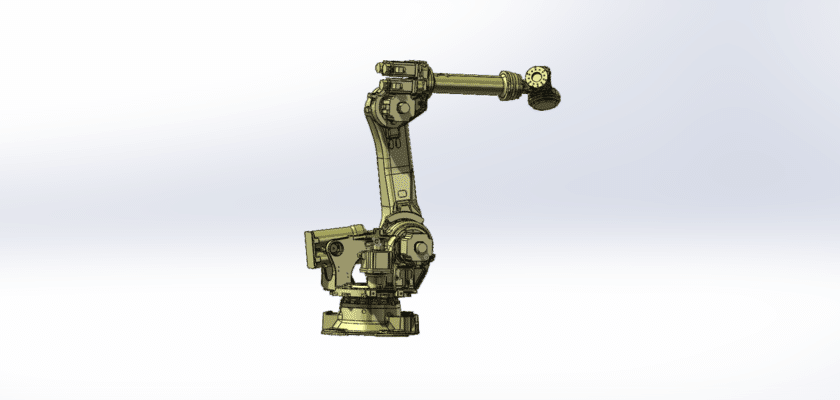
- Overall Configuration: A comprehensive view of the robot, highlighting its physical dimensions and layout, often represented in a 3D perspective to illustrate its range of motion.
- Robotic Arm Structure: Detailed illustrations of the robotic arm, which consists of:
- Links: Individual segments of the arm that connect the various joints.
- Joints: Types of joints (e.g., revolute) that allow for rotation and flexibility, enabling complex movements in multiple directions.
- Degrees of Freedom: Specifications indicating the six degrees of freedom provided by the robot, which allows for a wide range of motion and the ability to perform intricate tasks.
- End Effector Design: Descriptions of the tool or gripper attached to the robotic arm, including:
- Gripper Mechanism: Information on the design and functionality of the gripper, which can be used for tasks like picking, placing, or manipulating various objects.
- Interchangeable End Effectors: Details on the ability to switch between different tools depending on task requirements, such as welding torches, suction cups, or specialized manipulators.
- Control System: Details about the control unit that manages the robot’s operations, including:
- Robot Controller: Information on the type of controller used for programming and controlling the robot’s movements.
- User Interface: Illustrations of control panels or software interfaces that allow operators to easily program tasks, adjust parameters, and monitor performance.
- Sensors and Feedback Systems: Diagrams showing integrated sensors that provide real-time feedback on the robot’s position, orientation, and interaction with its environment, enhancing accuracy and safety.
- Safety Features: Information on safety mechanisms, such as:
- Emergency Stop Buttons: Descriptions of emergency stop systems and protocols to ensure safe operation.
- Protective Barriers: Information on safety enclosures or light curtains designed to protect operators from potential hazards.
- Power Supply: Information about the power source, including:
- Electrical Specifications: Details on the type and capacity of the power supply used for the robot’s operation.
- Mobility Mechanism: Information on the robot’s base design, which may include:
- Stationary or Mobile Base: Diagrams indicating the stability of the system during operation and options for mobility if applicable.
- Maintenance Access Points: Guidance on areas designed for easy access during maintenance and repair, facilitating efficient servicing of the robot.
- Performance Specifications: Summary of key performance metrics, such as payload capacity, speed, precision, and operational range, providing essential information for operational planning.
- Application Context: Brief descriptions of typical applications for the 6-axis robot, highlighting its versatility across various industries, including automotive manufacturing, electronics assembly, food processing, and more.
This drawing serves as a crucial reference for anyone involved in the operation and maintenance of six-axis robotic systems, ensuring effective performance, reliability, and adherence to industry standards in automation and robotics.