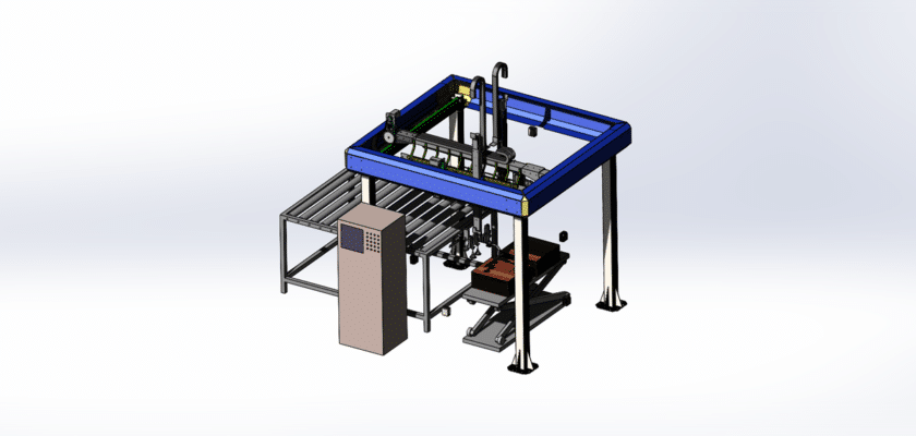
A Robot Flat Loading Drawing is a detailed technical illustration that depicts the design, components, and operational workflow of a robotic system specifically designed for the automatic loading of flat materials, such as sheets, plates, or panels. This drawing is essential for engineers, operators, and technicians involved in the development, operation, and maintenance of automated flat loading systems.
Key Features:
- Overall Layout: A comprehensive view of the entire flat loading system, showcasing the arrangement of robots, loading stations, and associated equipment within the operational area.
- Robotic Arms: Detailed illustrations of the robotic arms used for loading flat materials, including:
- Arm Configuration: Information about the structure, links, and joints of the robotic arms, highlighting their degrees of freedom for precise and flexible movements.
- End Effectors: Descriptions of specialized tools or grippers designed for handling flat materials, such as suction cups, clamps, or specialized fixtures that ensure secure handling.
- Loading Mechanism: Diagrams illustrating the mechanism used to load flat materials onto machines or into storage, including:
- Conveyor Systems: Details on conveyor belts or rollers that transport flat materials to and from the loading area.
- Orientation Systems: Information on systems that ensure flat materials are correctly oriented before loading.
- Control Systems: Information about the central control unit managing the automated loading processes, including:
- Programmable Logic Controllers (PLC): Descriptions of PLCs or industrial computers used for coordinating robot movements and loading operations.
- User Interface: Illustrations of control panels or software interfaces that allow operators to program tasks, monitor performance, and make adjustments.
- Safety Features: Information on safety mechanisms integrated into the system, such as:
- Emergency Stop Systems: Details on emergency stop buttons easily accessible near the loading area.
- Safety Guards and Sensors: Information on protective barriers, light curtains, and sensors designed to enhance operator safety during operation.
- Material Fixtures: Illustrations of fixtures or supports used to stabilize flat materials during loading, ensuring accuracy and preventing damage.
- Integration with Other Systems: Information on how the flat loading system integrates with other automated processes, such as CNC machines, cutting systems, or assembly lines, to streamline workflow.
- Quality Control Systems: Descriptions of integrated quality control measures, including:
- Inspection Stations: Information on sensors or cameras that verify the correct loading and positioning of flat materials.
- Testing Equipment: Details on any testing apparatus used to ensure the quality of the loaded materials.
- Maintenance Access Points: Guidance on areas designed for easy maintenance and repair, facilitating efficient servicing of the robotic equipment.
- Performance Specifications: Summary of key performance metrics, such as loading speed, accuracy, and operational efficiency, providing essential information for optimization.
- Application Context: Brief descriptions of typical applications for automated flat loading systems across various industries, including manufacturing, metalworking, packaging, and logistics.
This drawing serves as a vital reference for anyone involved in the design, operation, and maintenance of robotic flat loading systems, ensuring effective performance, reliability, and adherence to industry standards in automated material handling.