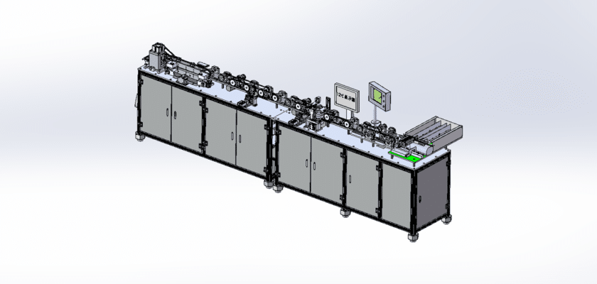
A Resistor Component Inspection Line Drawing is a technical illustration that outlines the layout and components of a production line dedicated to the inspection of resistor components. This drawing is essential for ensuring quality control and operational efficiency in manufacturing processes.
Ключевые особенности:
- Станции инспекции: Diagrams showing multiple stations along the inspection line where resistors are evaluated, each equipped with fixtures or holders to secure the components during testing.
- Автоматическая система подачи: Representation of the conveyor or automated transport system that moves resistors from one inspection station to the next, ensuring a continuous flow of parts.
- Испытательное оборудование: Details about the measurement devices used to evaluate resistor parameters, such as resistance value, tolerance, and thermal performance, including multimeters or specialized testing rigs.
- Блок управления: Information on the central processing unit that manages the inspection workflow, records measurements, and analyzes data for quality assurance.
- Пользовательский интерфейс: Illustrations of the control panel or touchscreen that allow operators to monitor the inspection process, set parameters for testing, and view real-time results.
- Системы вывода данных: Diagrams showing how inspection results are logged and communicated, including digital displays for immediate feedback, data storage systems for analysis, and connections for external reporting.
- Механическая конструкция: Information about the structural components that provide support and stability to the inspection line, ensuring precise operation and minimal vibration.
- Источник питания: Подробная информация о требованиях к электропитанию, включая электрические соединения и любые резервные системы для обеспечения надежной работы.
This drawing serves as a comprehensive reference for engineers and technicians involved in the design, assembly, and maintenance of resistor component inspection lines, ensuring high standards of quality control and efficiency in manufacturing processes.