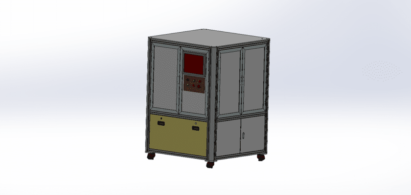
Чертеж машины для автоматического визуального контроля — это техническая иллюстрация, на которой изображены компоненты и компоновка машины, предназначенной для автоматизированного визуального контроля изделий или компонентов.
Ключевые особенности:
- Станция инспекции: Схемы, показывающие область, где располагаются предметы для визуального осмотра, часто с регулируемыми приспособлениями или конвейерными системами для обеспечения правильного выравнивания.
- Система камер: Изображение камер, используемых для захвата изображений, включая их размещение, объективы и любые системы освещения (например, светодиоды), которые улучшают качество изображения.
- Блок обработки изображений: Подробная информация о блоке обработки, который анализирует полученные изображения, используя алгоритмы для обнаружения дефектов, измерения размеров и оценки общего качества.
- Пользовательский интерфейс: Иллюстрации панели управления или сенсорного экрана, позволяющие операторам контролировать процесс проверки, задавать параметры и просматривать результаты проверки в режиме реального времени.
- Системы вывода данных: Диаграммы, показывающие, как передаются результаты проверки, например, с помощью цифровых дисплеев, оповещений о дефектах или систем регистрации данных для анализа качества.
- Механическая система обработки: Информация о конвейерной ленте или роботизированных манипуляторах, которые транспортируют изделия через зону досмотра, обеспечивая бесперебойную и эффективную работу.
- Источник питания: Подробная информация о требованиях к электропитанию машины, включая электрические соединения и любые резервные системы для обеспечения непрерывной работы.
Данный чертеж служит всеобъемлющим справочным материалом для инженеров и техников, занимающихся проектированием, сборкой и обслуживанием автоматических машин визуального контроля, обеспечивая эффективный контроль качества и эксплуатационную эффективность производственных процессов.