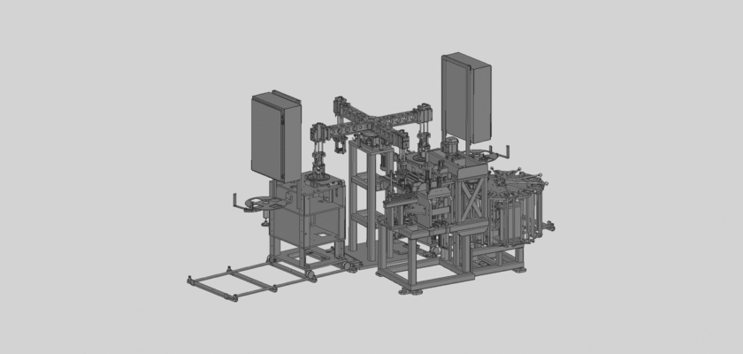
Испытайте новый уровень автоматизации сборки с нашими профессионалами Двухбашенный сборочный станок на заказ рисунок, доступный для бесплатная загрузка! Этот подробный технический чертеж подробно описывает высокоскоростную двухстанционную сборочную систему, предназначенную для решения сложных производственных задач с исключительной эффективностью. Этот чертеж — бесценный ресурс для инженеров, руководителей производства и студентов, стремящихся понять, как две независимые вращающиеся револьверные головки могут работать в идеальной гармонии при сборке изделий. Он подробно описывает сложные механизмы, от индексных приводов и инструментальных станций до роботизированных рук и систем подачи. Загрузив этот чертеж, вы получите ценное представление о принципах синхронизированной автоматизации, где несколько операций выполняются одновременно, что значительно сокращает время цикла и повышает производительность. Независимо от того, являетесь ли вы профессионалом, оптимизирующим производственный цех, или студентом, изучающим передовые производственные технологии, этот документ станет ключевым источником информации для освоения процессов крупносерийной сборки.
Ключевые особенности:
- Индексация с двумя башнями: На чертеже наглядно показаны две независимые, высокоскоростные вращающиеся револьверные головки. Такая двухпозиционная конструкция позволяет выполнять операции одновременно. Пока одна револьверная головка загружает компонент, другая выполняет сборку или проверку, обеспечивая непрерывное производство и максимальную эффективность.
- Синхронизированное управление движением: На чертеже показана усовершенствованная система управления, которая точно координирует движения обеих револьверных головок и связанного с ними инструмента. Эта синхронизация критически важна для предотвращения столкновений и обеспечения сборки каждой детали с точностью до миллиметра даже на высоких скоростях.
- Индивидуальные инструменты и приспособления: На чертежах подробно показано, как специализированные инструменты, такие как захваты, отвёртки и прессы, устанавливаются на каждой револьверной станции. Модульная конструкция позволяет быстро перенастраивать станок для обработки различных изделий, что делает его универсальным решением для самых разных сборочных задач.
- Интегрированное кормление и инспекция: Чертеж включает в себя подробные схемы автоматизированных систем подачи деталей (например, вибрационных чаш, питателей) и интегрированных систем технического зрения. Совместная работа этих компонентов обеспечивает правильное размещение деталей и соответствие каждой готовой сборки строгим стандартам качества.