A Multi-Link Robot Drawing is a detailed technical illustration that depicts the design, components, and functionalities of a multi-link robotic system, which is used in various applications such as automation, manufacturing, and research. This drawing is essential for engineers, developers, and operators involved in the design, operation, and maintenance of multi-link robots.
Ключевые особенности:
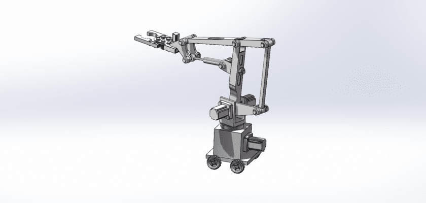
- Общая планировка: A comprehensive view of the multi-link robot, showcasing its structure and the arrangement of key components in a typical operational environment.
- Linkage Structure: Detailed illustrations of the robot’s segments, including:
- Links: Information about the individual segments (links) of the robot, which connect at joints to form the robotic arm.
- Joints: Descriptions of the types of joints (e.g., revolute, prismatic) that allow for various movements and flexibility.
- Степени свободы: Specifications indicating the number of degrees of freedom provided by the multiple links, allowing the robot to perform complex tasks and reach a wide range of positions.
- Конечный эффектор: Descriptions of the tool or gripper attached to the end of the robot arm, including:
- Конструкция захвата: Details on the design and functionality of the end effector for specific applications such as handling, welding, or painting.
- Сменные инструменты: Information on the capability to switch between different end effectors based on task requirements.
- Система управления: Подробная информация о блоке управления, который управляет работой робота, включая:
- Controller Specifications: Information on the controller used for programming and controlling the robot’s movements and tasks.
- Пользовательский интерфейс: Illustrations of control panels or software interfaces that allow operators to program tasks and monitor performance.
- Actuators and Motors: Information on the types of actuators used for movement, including:
- Servo Motors and Stepper Motors: Specifications on the motors that drive the joints and provide precise control over movements.
- Датчики и системы обратной связи: Diagrams showing various sensors integrated into the robot, such as:
- Датчики положения: Used for feedback on the joint angles and position of each link.
- Force Sensors: To detect the amount of force being applied during operations.
- Источник питания: Информация об источнике питания, включая:
- Характеристики аккумулятора: Details on the type and capacity of batteries used, ensuring reliable operation.
- Функции безопасности: Information on safety mechanisms, such as emergency stop functions, collision detection systems, and protective enclosures to ensure safe operation in various environments.
- Возможности подключения: Информация о возможностях связи, в том числе:
- Беспроводная связь: Подробная информация о подключении по Bluetooth или Wi-Fi для удаленного управления и обмена данными.
- Интеграция с другими системами: Information on how the robot can communicate with external devices or networks for enhanced functionality.
- Точки доступа для обслуживания: Руководство по зонам, предназначенным для легкого доступа при техническом обслуживании и ремонте, что способствует эффективному обслуживанию робота.
- Технические характеристики: сводка ключевых показателей производительности, таких как грузоподъемность, вылет, скорость и точность, предоставляющая важную информацию для оперативного планирования.
- Контекст приложения: Brief descriptions of typical applications for multi-link robots, such as in automotive assembly, packaging, material handling, and research laboratories.
This drawing serves as a vital reference for anyone involved in the operation and maintenance of multi-link robots, ensuring effective performance, reliability, and adherence to industry standards across various automation applications.