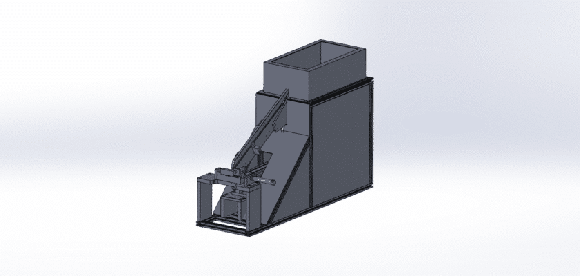
A screw feeding mechanism is an essential component in modern automated assembly lines. It streamlines the process of dispensing screws, significantly boosting production speed and accuracy. This system eliminates the tedious and error-prone task of manual screw handling, ensuring a continuous and consistent supply of fasteners to the assembly point. Our free CAD drawing provides a detailed look at the core components and design principles of this ingenious device, allowing you to understand its operation and integrate it into your own projects. Whether you are a student, hobbyist, or professional engineer, this drawing is a valuable resource for designing, studying, or modifying your own automated systems.
The mechanism operates on the principle of sorting, orienting, and feeding screws one by one. Typically, it uses a vibratory bowl feeder to agitate and align the screws, directing them down a rail. A sensor or gate then releases a single screw at a time, often using a blast of air, to a pickup point. The system is designed to be highly reliable, minimizing jams and ensuring a smooth workflow. By automating this repetitive process, it drastically reduces labor costs and human fatigue while maintaining a high standard of quality and consistency in manufacturing.
Key Features:
- Automated Feeding: Provides a continuous, on-demand supply of screws to the assembly head.
- High-Speed Operation: Drastically cuts down on cycle times compared to manual methods.
- Precision and Reliability: Ensures accurate screw placement and reduces assembly errors.
- Versatile Design: Can be adapted to handle various screw sizes and types, from micro screws to larger bolts.
- Easy Integration: The design can be easily incorporated into robotic arms, automated workstations, and other assembly systems.