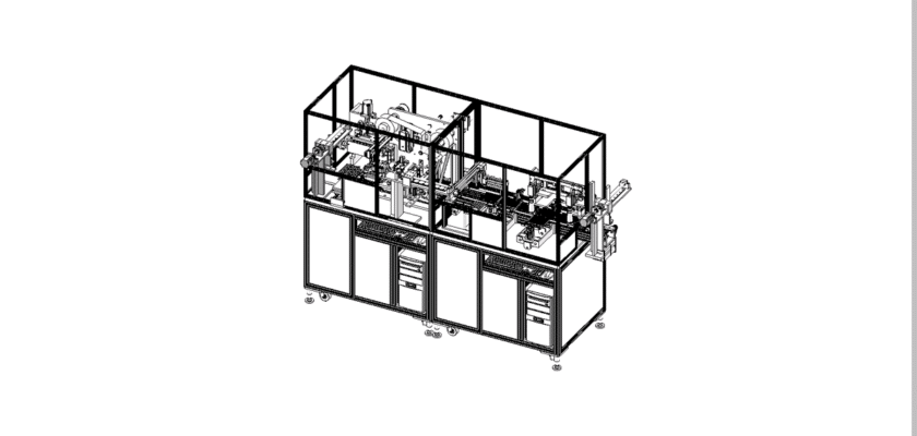
A Three-Pin Shaft Ball Diameter Detection Drawing is a technical illustration that outlines the components and layout of a system designed to measure the diameter of balls on three-pin shafts. This type of system is critical for quality control in manufacturing processes where precision is essential.
Key Features:
- Measurement Station: Diagrams showing the designated area where three-pin shafts are positioned for diameter measurement, featuring fixtures that securely hold the shafts during the detection process.
- Measurement Sensors: Representation of the sensors or gauges used to accurately measure the diameter of the balls, such as laser measurement systems, calipers, or specialized probes.
- Control Unit: Information on the central processing unit that manages the measurement operations, records data, and analyzes measurements for compliance with specifications.
- User Interface: Illustrations of the control panel or touchscreen that allow operators to monitor the measurement process, set parameters, and view real-time results.
- Data Output Systems: Diagrams showing how measurement results are communicated, including digital displays for immediate feedback, data logging for tracking quality metrics, and connections for reporting to external systems.
- Mechanical Framework: Information about the structural components that support the measurement system, ensuring stability and precision during operation.
- Power Supply: Details regarding the power requirements, including electrical connections and any backup systems to ensure reliable operation.
This drawing serves as a comprehensive reference for engineers and technicians involved in the design, assembly, and maintenance of three-pin shaft ball diameter detection systems, ensuring high standards of quality control and operational efficiency in manufacturing processes.